1 - Introduction
Power production and other use of fossil energy are the largest sources of greenhouse gas emissions globally. Capture and storage of CO2 in geological formations represent an important measure with a great potential to reduce global emissions. In its Special Report on Carbon Dioxide Capture and Storage (2005), the United Nations Intergovernmental Panel on Climate Change (IPCC) concludes that capture and storage of CO2 may account for as much as one half of emission reductions in this century. However, major challenges must be solved before this potential can be realized. The IPCC report points out that there is as yet no experience with CO2 capture from large coal and gas power plants.
Norway has extensive experience with storage of CO2 in geological structures. Since 1996, approximately 1 Mt of CO2 have been separated from gas production annually at the Sleipner Vest Field in the North Sea for storage in the Utsira formation, a geological formation more than 800 metres below the seabed. From 2014 a further 0.1-0.2 Mt of CO2 from the newly developed Gudrun Field will be injected into the same formation every year.
In connection with treatment of the well stream from the Snøhvit Field and the LNG production on Melkøya in the Barents Sea, about 0.7 Mt of CO2 have been safely injected and stored in the Tubåen sandstone annually. The Tubåen Formation is about 2 300 metres beneath the seabed, and CO2 has been injected since 2008. CO2 is removed from the gas stream onshore and piped 153 km back to the field. In early 2010 the field operator announced that they now realized there was less storage capacity than first expected at the Snøhvit injection site. Therefore the injection site was moved from the Tubåen Formation to the Stø Formation in 2011.
There is significant technical potential for storing CO2 in geological formations around the world. Producing oil and gas fields, abandoned oil and gas fields and geological formations such as saline aquifers might all be candidates for such storage. Storage in reservoirs that are no longer in operation can be a good solution in terms of geology, since these structures are likely to be impermeable after having held oil and gas for millions of years.
Environmentally sounds storage of CO2 is a prerequisite for a successful CCS chain. Consequently, the mapping, qualification and verification of storage sites are indispensable for CCS as a climate change mitigation measure. Geological formations offshore Norway are expected to be well-suited for storing large quantities of CO2, and it is important to have the best possible understanding of the CO2 storage potential.
These factors necessitate an enhanced effort to map and investigate CO2 storage sites. The production of this CO2 storage atlas is at the very centre of this effort. Various Norwegian research institutions and commercial enterprises have extensive experience and competence within CO2 storage.

Fig.1.1
Snøhvit: There is capacity for separation and storage of 700 000 tons annually in water-saturated sandstone reservoirs under the Snøhvit Field in the Barents Sea. A shale cap which lies above the sandstone will seal the reservoir and ensure that the CO2 stays underground.

Fig.1.2
Snøhvit licence and Sleipner licence

Fig.1.3
Sleipner: More than 13 million tons of carbon dioxide are now stored in the Utsira Formation in the North Sea. Every year since 1996, one million tons of carbon dioxide have been captured from natural gas production at the Sleipner Field and stored in an aquifer more than 800 metres below the seabed. The layer contains porous sandstone filled with saline water.
CLIMIT PROGRAMME

CLIMITCLIMIT is the national programme for research, development and demonstration of technologies for CO2 capture and storage (CCS) from power generation and industry.
The program covers both the Research Council of Norway’s support scheme for research and development (CLIMIT R&D) and Gassnova’s support scheme for development and demonstration of technology for CO2 capture and storage (CLIMIT Demo).
The CLIMIT programme is leading a portfolio of projects in all stages of the development chain. The programme focuses on the development of knowledge, technology and solutions to reduce costs and to stimulate broad international implementation of CCS. Furthermore CLIMIT shall leverage national advantages and the development of new technology and service concepts with international potential.
The programme is aimed at Norwegian companies, research institutions and universities, preferably in cooperation with industry and international research institutions which can contribute to accelerate CCS commercialisation.
CLIMIT has the following objectives:
EFFECT-ORIENTED GOALS
- Lower costs and earlier international realisation of CCS.
- CCS in Norwegian enterprises.
- Realisation of the storage potential in the North Sea
RESULT OBJECTIVES
Knowledge and expertise to close technology gaps and increase safety.
Ground-breaking technologies and service concepts with international potential.
CLIMIT has three focus areas and targets national players with CCS potential. Environmental issues are covered in all three areas:
- New innovative solutions that can give considerable cost reductions and increased safety.
- Areas where Norway or Norwegian companies have advantages in CCS.
- CCS in Norwegian industry with major CO2 emissions.
CO2 STORAGE
Projects supported by CLIMIT will contribute to the safe and cost-efficient implementation of CO2 storage in accordance with regulatory requirements and international agreements.
Key topics within CO2 storage are i) the development of further methods to estimate and utilize the storage capacity on the continental shelf and ii) the development of methods and technology to develop storage locations, safe injection and appropriate monitoring technology.
CO2 storage in combination with CO2 used for enhanced oil recovery is also an important focus area.
UNIS CO2 Lab - by Alvar Braathen and co-workers

The UNIS CO2 Lab in Longyearbyen, Svalbard, Norway, is one of the demonstration projects currently carried out worldwide. The purpose is to learn more about CO2 behaviour in high-pressure conditions and to assess the storage and sealing capacity of local subsurface rock successions.
These pilot projects are meant to provide a foundation for worldwide commercial ventures of CO2 sequestration.
Longyearbyen has a population of around 2000 and is located in the polar wilderness of central Spitsbergen.
A coal-burning, single power plant in Longyearbyen provides both electricity and hot water and supports the city’s entire house-heating system of radiators. One objective of the demonstration project is to investigate if there is sufficient storage capacity close to Longyearbyen to capture the CO2 which can be sequestered from the power plant – a maximum of 60,000 tons /annually.
The aim of the project has been to evaluate local geological conditions for subsurface storage of the greenhouse gas CO2. Project activity included drilling and logging of slim-hole cored wells, acquisition of seismic sections with snow streamer and a wide range of laboratory and field studies. The targeted reservoir is a paralic sandstone succession of the Upper Triassic−Middle Jurassic Kapp Toscana Group at ≥670 m depth. This is overlain by thick Upper Jurassic shales and younger shale-rich formations. The reservoir has a sandstone net gross ratio of 25−30% and is intruded by thin dolerite sills and dykes. The reservoir and cap-rock succession rise at 1−3° towards the surface and crop out 14−20 km to the northeast of Longyearbyen. Near the surface, all units appear to be sealed by permafrost. The reservoir is compartmentalized and shows considerable underpressure, in the lower part equal to 30% of hydrostatic pressure, which indicates good initial sealing conditions. Core samples indicate a reservoir with sandstones of moderate porosity (5−18%) and low permeability (max. 1−2 mD). Rock fractures are therefore important for fluid flow.
Water injection tests have indicated good injectivity in the lower part of the reservoir succession (870−970 m depth). The relatively more porous and permeable upper part (670−870 m depth) has only been partly tested. The injectivity increases with increasing pressure, suggesting that the fractures gradually open and grow under injection. Reservoir pressure compartments indicate bedding-parallel permeability barriers, although these may gradually yield under a growing cumulative pressure. The reservoir storage capacity and its apparent connection with the surface remain to be fully evaluated. However, the lateral expansion of the injected CO2 plume in this large reservoir over a distance of 14 km to the outcrops, is projected to take thousands of years.

Fig.1.5
Results from Drillhole 4 in the UNIS CO2 Lab.
The Norwegian Continental Shelf
Petroleum activity in the Norwegian Continental Shelf (NCS) is restricted to the North Sea, the Norwegian Sea and the southern Barents Sea. These regions contain several aquifers at a suitable depth for CO2 storage, and are also considered the most favourable for large scale CO2 sequestration. The depth to the Base Cretaceous Unconformity (BCU) gives an indication of the major structural elements. Jurassic aquifers occur below the BCU in most of the NCS. Jurassic shales are the source rocks for most of the hydrocarbons generated in the North Sea and Norwegian Sea, They can be considered to be mature in the blue areas of the map, below approximately 4000 m. Most of the oil and gas fields in these regions are located within migration distance from these areas.
The Norwegian continental shelf belongs to three different geological provinces. The northern North Sea is a subsiding basin developed above the continental Paleozoic and Mesozoic rift between UK and Norway. The Base Cretaceous unconformity (BCU) marks the end of the last major rifting event and the top of the cap rock of the Jurassic aquifers. Younger sediments in the North Sea Basin were sourced from all land masses surrounding the basin and contain several important aquifers.
The Norwegian Sea shelf faces the oceanic crust in the Norwegian-Greenland Sea. The BCU is very deeply buried in the deep waters beyond the shelf slope. The map does not display the BCU at greater burial depths than 5000 m, as these depths are not relevant for CO2 injection. The main aquifers suitable for CO2 injection in the Norwegian Sea shelf belong to the Jurassic section. The storage capacities of the Møre Basin and the Lofoten-Vesterålen area were not studied. The geology of these areas is considered to be less favourable for storage of large volumes of CO2 than the evaluated areas.
The Barents Sea shelf was filled in by thick sequences of Upper Paleozoic, Mesozoic and younger rocks following a major Carboniferous rifting phase. In the Norwegian sector, petroleum activity has been concentrated to the south-western part, which is made up by platforms, shallow basins and highs. The main aquifers consist of Jurassic and Triassic sediments. In the western margin, west of the mapped area in the figure, these sediments are too deeply buried to be suitable for CO2 storage. The study area was exposed to deep erosion in the Cenozoic and in the Quaternary. Because reservoir properties reflect maximum burial and not the present burial, aquifers with good storage potential are located at relatively shallow depths.


Fig.1.6
Area status for the Norwegian Continental Shelf March 2012
(Source: NPD Facts 2013)

Fig.1.7
Depth map of The Base Cretaceous Unconformity and areas evalu- ated in the Atlas. The boundaries to oceanic crust and main volcanic provinces are indicated.
Naturally occurring CO2
CO2 occurs in some metamorphic rocks and is an integrated component in intrusive and extrusive volcanic rocks. The gas exported from Norway to the European continent cannot have more than 2.5% CO2. Some producing gas fields in the Norwegian Continental Shelf have a higher CO2 content which requires dilution with gas that has a low CO2 content, or CO2 has to be separated from the gas stream and injected into saline aquifers. Gas from the Snøhvit Field and the Sleipner Field has high CO2 concentrations that require CO2 capture and storage. Some discoveries in the Norwegian Sea offshore Nordland also have a high CO2 content that will require CO2 capture and storage if the gas is produced. CO2-rich gas occurs in the western parts of the Halten- and Dønna Terraces. In the western part of the Vøring Basin, one well showed a CO2 content of 7%. Other gas discoveries in the deeper parts of the Møre- and Vøring Basins do not show significant CO2 content. The dots on the map show the location of exploration wells where CO2 content higher than 3 % has been encountered in gas discoveries. In a few wells, CO2 values range between 10 and 20 %. There are many wells where the CO2 concentration was not measured, but the map gives an indication of the areas which can become future sources of CO2.
In general on the Norwegian shelf, the percentage of CO2 associated with methane in gas fields can be correlated with the burial depth of the source rock which has generated the gas. In the Barents Sea, CO2 rich gas has been encountered along the margins of the deep Harstad, Tromsø and Bjørnøya Basins. One accumulation of gas with a CO2 content in the order of 50% was found in well 7019/1-1 (NPD website), while in other gas discoveries in the western Barents Sea, the percentage of CO2 typically does not exceed 10. Further east, the CO2 content appears to be lower. The reason for the increased CO2 content in those areas is not clear, although the close vicinity to Paleogene volcanic sill intrusions may explain the amount of natural CO2 in 7019/1-1. Both organic processes and degassing of metamorphic and overheated sedimentary rocks may contribute to the CO2 generation.

Fig.1.8
A selection of wellbores with CO2 content above 5%.
Based on data from NPD fact pages.
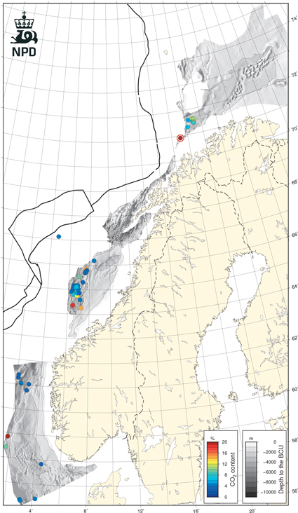
Fig.1.9
Map of Base Cretaceous unconformity showing location of exploration wells where the measured CO2 concentration in natural gas exceeds 3 %. 7019/1-1 is marked by a red ring. Residual oil zones are indicated by squares. Based on data from NPD fact pages.
Download figures from this chapter